

Process Control Valves: A Complete Guide to Industrial Flow Management
- Valve
- Oct 14, 2026
- 14 Views
Process Control Valves: A Complete Guide to Industrial Flow Management
Modern industrial operations depend on accurate control of liquids, gases, steam, and other process media. Industries such as oil and gas, chemical processing, pharmaceuticals, power generation, water treatment, and food manufacturing require reliable equipment to maintain consistent operating conditions. Flow regulation is especially important because even minor variations in pressure, temperature, or flow rate can affect product quality, energy consumption, and operational safety. Control valves are essential components in these systems because they regulate the movement of process fluids according to specific operating requirements.
Process control valves are designed to adjust fluid flow automatically or manually to maintain desired process conditions. They work alongside sensors, controllers, and other instrumentation to support stable and efficient industrial operations. Depending on the application, these valves can regulate flow, manage pressure, control temperature indirectly, and maintain liquid levels within specified limits. Selecting the appropriate valve requires an understanding of operating conditions, material compatibility, pressure requirements, and control accuracy. With suitable design and maintenance, industrial valves can improve productivity, reduce unnecessary energy consumption, and support dependable plant performance.
What Are Process Control Valves?
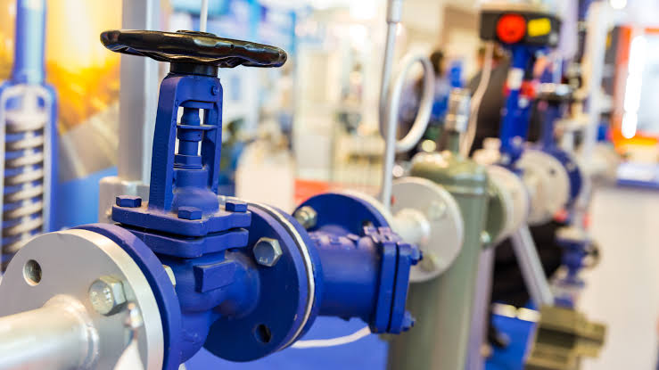
Process control valves are mechanical devices used to regulate the flow of fluids through industrial pipelines. They operate by changing the size of the opening through which a liquid, gas, or steam passes. This adjustment influences the flow rate and, depending on the system, can also affect pressure, temperature, and liquid level. These valves are commonly integrated into automated control loops that continuously monitor process conditions and make adjustments whenever the measured values differ from their required setpoints.
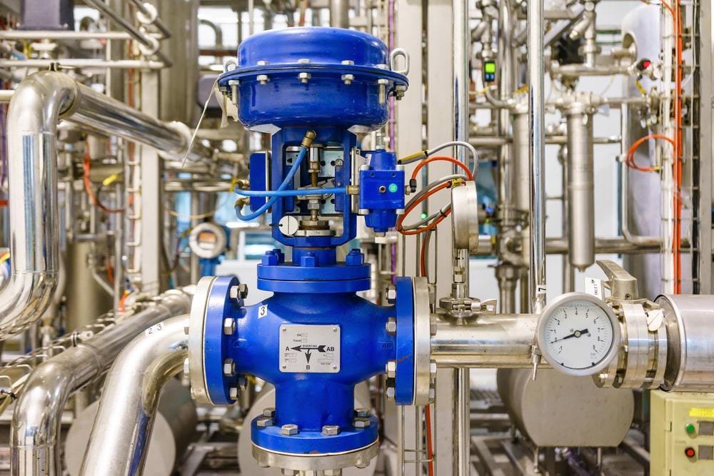
A typical control valve assembly consists of a valve body, an internal closing element, a stem, and an actuator. Depending on the design, it may also include a positioner and supporting accessories. The actuator moves the valve according to a signal received from the control system, while the positioner helps ensure that the valve reaches the requested position. Different designs are available for applications involving corrosive chemicals, high temperatures, high pressures, abrasive fluids, and demanding flow conditions. Choosing the right assembly helps maintain process stability, protect equipment, and improve the reliability of industrial production systems.
How Do Process Control Valves Work?
The working principle of a control valve involves receiving a control signal and adjusting the internal passage to regulate fluid movement. In an automated system, sensors measure a process variable such as flow rate, pressure, temperature, or liquid level. A controller compares the measured value with the desired setpoint and sends a corrective signal to the valve actuator. The actuator then changes the valve opening to increase or decrease the flow, helping bring the process back toward its target condition.
For example, in a steam heating system, a temperature sensor measures the temperature of the equipment or material being heated. If the temperature falls below the setpoint, the controller may command the steam valve to open further. When the temperature approaches the target, the valve adjusts to reduce the steam supply. This continuous process supports consistent operating conditions and reduces the need for frequent manual intervention. Depending on the application, actuators may use pneumatic, electric, or hydraulic power. Correct valve sizing, suitable control characteristics, and proper instrument calibration are important for achieving stable control without excessive fluctuations or unnecessary wear.
Major Types of Industrial Control Valves
Different industrial applications require different valve designs. The selection depends on the type of fluid, required flow capacity, operating pressure, temperature, leakage requirements, and control accuracy. Some valves are designed for precise throttling, while others are better suited to large pipelines or applications where pressure drop must be minimized. Understanding the main valve types helps engineers and plant operators select equipment that meets the technical requirements of their processes.
The most commonly used designs include globe valves, ball valves, butterfly valves, diaphragm valves, and plug valves. Each type has specific advantages and limitations. Globe valves are frequently used for accurate throttling, while properly designed ball valves can provide effective flow control and tight shutoff. Butterfly valves are often selected for large-diameter pipelines because of their compact construction. Diaphragm valves are useful in applications requiring isolation of the operating mechanism from the process fluid. Plug valves are used in selected industrial services where their construction and flow characteristics suit the application. The final choice should be based on operating data rather than price or valve appearance alone.
1. Globe Control Valves
Globe valves are widely used where accurate regulation of flow is required. Their internal design allows a movable plug or disc to change the opening between the valve plug and seat. This arrangement provides controlled throttling and can support stable adjustment across a range of operating conditions. Globe valves are commonly found in steam systems, chemical processing facilities, power plants, and industrial heating applications.
Their main advantages include predictable control characteristics, suitability for many demanding services, and the availability of different trim designs. However, globe valves may create a relatively high pressure drop compared with some other valve types. They can also require more installation space and may involve higher maintenance costs in certain applications. Engineers should consider flow capacity, cavitation risk, noise, and actuator requirements before selecting a globe valve for a specific process.
2. Ball Control Valves
Ball valves use a rotating spherical closure element with a passage through its center. Standard ball valves are commonly used for on-off service, but specially designed control ball valves can regulate flow effectively. Their compact design, quick operation, and relatively low flow resistance make them useful in numerous industrial systems. Depending on the construction and materials, they can handle different liquids, gases, and selected chemical services.
Control ball valves may incorporate characterized balls, V-shaped openings, or other design features that provide more suitable throttling characteristics. These features allow the valve to adjust flow more predictably than a conventional full-port ball valve used outside its intended operating range. Important selection factors include seat material, pressure rating, temperature limits, leakage requirements, and actuator torque. In applications involving continuous modulation, the valve must be specifically rated for control duty to reduce the risk of unstable operation and premature wear.
3. Butterfly Control Valves
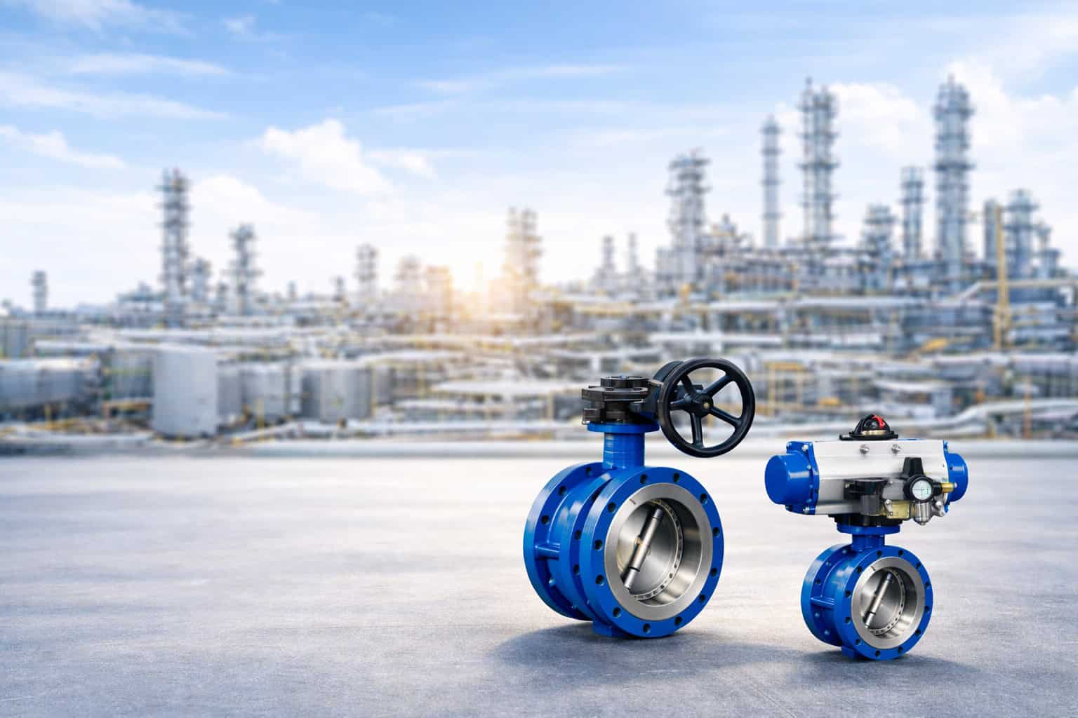
Butterfly valves regulate flow using a disc that rotates inside the pipeline. As the disc changes position, it changes the available flow passage and controls the amount of fluid passing through the valve. These valves are often selected for large-diameter pipelines because they are compact, comparatively lightweight, and generally require less installation space than some alternative designs.
Butterfly control valves are used in water treatment, HVAC systems, industrial cooling circuits, power generation, and selected chemical processing applications. Their performance depends on the disc design, seat material, actuator arrangement, and operating conditions. High-performance and specialized butterfly valves may be suitable for demanding pressure and temperature requirements, but not every design is appropriate for every service. Engineers should evaluate control accuracy, shutoff performance, fluid velocity, and cavitation or erosion risks when selecting a butterfly valve for continuous regulation.
4. Diaphragm Control Valves
Diaphragm valves use a flexible membrane that moves against a valve body or weir to regulate or stop fluid flow. This arrangement can separate the process fluid from certain operating components, making diaphragm valves useful in applications where contamination control and corrosion resistance are important. They are commonly used in pharmaceutical manufacturing, water treatment, food processing, and selected chemical applications.
The valve body and diaphragm materials must be compatible with the process fluid, cleaning chemicals, pressure, and temperature. These valves can be useful for handling certain corrosive or sensitive media, particularly when hygienic design is required. However, diaphragm materials have operating limits and may deteriorate if exposed to unsuitable chemicals or excessive temperatures. Regular inspection and timely replacement help maintain sealing performance and reduce the risk of process leakage.
5. Plug Control Valves
Plug valves use a cylindrical or tapered plug that rotates inside the valve body to control the flow passage. Although many conventional plug valves are intended primarily for isolation, specialized designs can also be used for regulating flow. Their suitability depends on the internal geometry, sealing arrangement, actuator, and characteristics of the process fluid.
These valves may be found in chemical plants, industrial processing facilities, and selected services involving liquids or gases. Some designs are useful when a simple quarter-turn operating mechanism is preferred. Before installation, engineers should assess pressure and temperature ratings, sealing performance, material compatibility, and the manufacturer's guidance on throttling duty. A valve intended only for on-off operation should not automatically be assumed to provide accurate or durable continuous flow control.
Key Components of a Control Valve Assembly
A complete valve assembly contains several components that work together to deliver the required control performance. The valve body provides the pressure-containing structure and forms the main flow passage. Internal trim components, including the plug, disc, ball, and seat depending on the design, determine how the flow is regulated. The stem or shaft transfers movement from the actuator to the closure element, while seals and packing help limit leakage around moving components.
The actuator supplies the force needed to move the valve. Pneumatic actuators use compressed air, electric actuators use an electric motor and associated mechanism, and hydraulic actuators use pressurized fluid. A positioner may be installed to compare the requested valve position with actual movement and make corrections. Additional accessories can include limit switches, solenoid valves, air filters and regulators, and position feedback devices. When these components are correctly selected and installed, the complete assembly can respond more accurately to control signals and support dependable industrial operation.
Applications of Process Control Valves Across Industries
Process control valves are used in industries where operating conditions must remain within defined limits. In oil and gas facilities, they regulate hydrocarbon flow, manage process pressure, and control utility systems. Chemical manufacturers use them to maintain appropriate flow rates during reactions, mixing, and material transfer. In power plants, control valves regulate steam, cooling water, and other fluids associated with energy generation. Their performance can directly affect process stability, operating efficiency, and equipment protection.
Water treatment plants use valves to manage filtration, chemical dosing, distribution, and wastewater treatment processes. Pharmaceutical facilities require carefully selected valve materials and hygienic designs to support product quality and cleaning requirements. Food and beverage manufacturers use suitable valves to control ingredients, water, steam, and cleaning fluids. In manufacturing plants, valves also support compressed air systems, thermal processing, and industrial cooling. Each application presents different challenges, so equipment selection should account for fluid properties, contamination risks, environmental conditions, and the consequences of control failure.
Benefits of Using Process Control Valves
Properly selected Process Control Valves offer several operational advantages by maintaining more consistent process conditions and allowing automated adjustments. Accurate flow regulation can help reduce material waste, improve product consistency, and limit unnecessary changes in pressure or temperature. In automated production facilities, these valves reduce the need for repeated manual adjustments and allow operators to manage complex processes through centralized control systems.
Another important benefit is the potential to improve energy efficiency. Correct valve sizing and appropriate control strategies can help prevent excessive pumping, unnecessary throttling losses, and unstable operation. Reliable shutoff capabilities can also reduce leakage when the selected design is suitable for the required isolation duty. In addition, modern valve assemblies can provide diagnostic information, position feedback, and integration with digital plant systems. These features help maintenance teams identify developing issues and plan inspections more effectively. The actual benefits depend on correct engineering, installation, calibration, and ongoing maintenance rather than the valve alone.
Factors to Consider When Selecting a Control Valve
Selecting a suitable valve requires a clear understanding of the process and its operating requirements. Engineers should evaluate the minimum, normal, and maximum flow rates, along with inlet and outlet pressures, temperature ranges, and the physical and chemical properties of the process medium. These parameters influence valve capacity, body materials, internal trim, sealing arrangements, and actuator selection.
Another important factor is the required control performance. Some applications need precise modulation over a wide flow range, while others primarily require reliable on-off operation. The valve's flow characteristic, rangeability, leakage class, and response time should match the control system's requirements. Additional considerations include available utilities, installation space, environmental exposure, maintenance access, and the consequences of a power or instrument-air failure.
Before finalizing a selection, consider the following points:
Flow capacity: Confirm the required minimum, normal, and maximum flow rates.
Pressure and temperature: Select components rated for the expected operating conditions.
Material compatibility: Ensure the body, trim, and seals can withstand the process fluid.
Actuator type: Choose pneumatic, electric, or hydraulic operation based on available utilities and control requirements.
Control characteristics: Match the valve's flow response to the process and controller.
Safety requirements: Determine the appropriate failure position and any necessary protective functions.
Maintenance needs: Check spare-part availability, accessibility, and expected service intervals.
Comparison of Common Control Valve Types
The following table provides a general comparison of common valve designs. Actual performance varies according to the specific model, trim, materials, and operating conditions.
Valve Type | Main Advantage | Common Applications | Important Consideration |
|---|---|---|---|
Globe valve | Accurate throttling | Steam and process control | Can produce higher pressure drop |
Ball valve | Low flow resistance in suitable designs | Gas and liquid systems | Control duty requires suitable design |
Butterfly valve | Compact and lightweight | Water and cooling systems | Performance depends on disc and seat design |
Diaphragm valve | Fluid separation from operating components | Pharmaceutical and chemical processes | Diaphragm has material and temperature limits |
Plug valve | Simple rotary mechanism | Selected industrial fluid services | Verify suitability for continuous modulation |
Importance of Valve Sizing and Flow Characteristics
Valve sizing is a critical engineering step because an incorrectly sized valve can create operational difficulties even when the valve itself is manufactured to a high standard. An oversized valve may operate close to its seat during normal conditions, making small movements produce disproportionately large changes in flow. This can cause poor controllability, cycling, and unnecessary wear. An undersized valve may not provide sufficient capacity during peak demand, resulting in excessive pressure loss or an inability to maintain the desired process condition.
Engineers typically use process flow data, pressure differentials, fluid density, viscosity, and other relevant properties to calculate the required valve capacity. Specialized calculations may also be needed for compressible gases, flashing liquids, or cavitating services. Flow characteristics, such as linear, equal-percentage, and quick-opening, describe how flow capacity changes with valve travel under specified conditions. Selecting an appropriate characteristic helps the valve respond effectively to process changes and improves overall control-loop performance.
Maintenance Practices for Reliable Valve Performance
Routine maintenance is essential for maintaining control accuracy and preventing unexpected equipment failures. Inspection schedules should be based on the valve's service conditions, operating history, manufacturer recommendations, and the criticality of the process. Maintenance teams should look for external leakage, abnormal noise, vibration, corrosion, actuator problems, and inconsistent valve movement. Instrument signals and position feedback should also be checked when the control response appears slower or less stable than expected.
Calibration and functional testing can identify problems with positioners, sensors, and actuators before they cause serious process interruptions. Depending on the service, maintenance may involve replacing seals, packing, diaphragms, or worn trim components. Valves exposed to abrasive fluids, corrosive chemicals, high temperatures, or frequent cycling may require more frequent inspection. Before maintenance begins, the equipment must be safely isolated, depressurized, and handled according to site procedures. Keeping accurate service records helps identify recurring faults and supports more effective maintenance planning.
Common Problems and Troubleshooting Methods
Control valve problems can arise from mechanical wear, incorrect sizing, poor installation, instrument faults, or unsuitable operating conditions. Hunting or repeated movement may indicate an unstable control loop, excessive actuator sensitivity, or unsuitable valve characteristics. Insufficient flow can result from incorrect sizing, blocked strainers, restricted piping, inadequate upstream pressure, or a valve that is not reaching its commanded position. Leakage may be associated with damaged seats, worn seals, incorrect installation, or unsuitable materials.
Troubleshooting should begin with a review of operating data and control-system signals rather than immediate component replacement. Operators should compare the requested valve position with actual feedback, inspect relevant pressure readings, and determine whether the issue originates in the valve, actuator, instrumentation, or wider process. Abnormal noise may require investigation of cavitation, flashing, high fluid velocity, or gas-flow effects. Serious faults should be assessed by qualified personnel, particularly where high pressure, hazardous chemicals, or hot fluids are involved. A structured troubleshooting process can reduce downtime and help prevent the same problem from returning.
Future Trends in Industrial Valve Technology
Industrial valve technology continues to evolve as manufacturers and plant operators focus on automation, reliability, energy efficiency, and predictive maintenance. Smart positioners and digital instruments can provide information about valve travel, operating cycles, actuator performance, and certain developing faults. When integrated with suitable control and asset-management systems, this information can help maintenance teams identify abnormal behavior before it leads to an unexpected shutdown.
Another important trend is the growing use of condition monitoring and data-driven maintenance planning. Instead of relying entirely on fixed inspection intervals, facilities can use equipment history and operating data to prioritize inspections according to risk. Improvements in materials, trim geometry, sealing technology, and actuator design also support demanding process conditions. However, digital monitoring does not eliminate the need for physical inspections, proper engineering, or safety procedures. The best results come from combining reliable valve design with appropriate instrumentation, trained personnel, and a well-managed maintenance strategy.
Conclusion
Industrial flow regulation is essential for maintaining productivity, safety, and consistent product quality across modern manufacturing and processing facilities. Choosing the correct valve requires careful evaluation of fluid properties, pressure, temperature, flow capacity, control accuracy, and operating conditions. Globe, ball, butterfly, diaphragm, and plug valves each offer different characteristics, making it important to match the design to the intended service.
Well-engineered Process Control Valves can support stable production, improve process efficiency, reduce material waste, and enable automated operation. Their long-term performance depends on accurate sizing, compatible materials, suitable actuators, proper installation, and regular maintenance. By combining the right valve technology with effective control systems and preventive maintenance practices, industrial facilities can achieve dependable flow management and improve overall operational performance.
Related Posts
- Sep 23, 2026
- SUDE
- 10